
History · Questions & answers (14)
RuttEtra — Help (v1.0)
ivo3d FX · RuttEtra · Match Name IVO3D RuttEtra · PiPL 16006 · binary version 524289
Scan-line relief in the spirit of the classic Rutt/Etra video synthesizer: the image is rebuilt from lines (or a grid, or a dot lattice), and each line is pushed sideways by the local luminance — bright areas raise the "terrain". On top of that, two FM waves ride on a shared phase: Path Wave bends the line's path, Intensity Wave stripes its brightness. The FM rule everywhere: brighter = higher frequency.
The plugin renders this model on the CPU, resolution-independent and deterministic (identical frames on every machine).
Since v0.4 the whole raster can be lifted into space: Render Mode: 3D Mesh turns every sample point into a vertex, sends the displacement into Z, and projects the result through an internal perspective camera. The 2D mode is untouched and stays the default.
Since v0.6 the same FM carrier can be sent through a filter and demodulated back: the Demodulator group transmits the line's luminance as a frequency, lowpasses the modulated carrier (not the picture), and recovers the value from the filtered phase. What the filter takes away comes back as overshoot and ringing in the terrain — the analog artifact, which is the point. This is a Classic 2D feature and it is off by default.
Since v0.8 the whole thing is considerably faster — Input Smooth in particular, which used to be the most expensive control by a wide margin and now costs the same whatever you set it to. The same round added two controls that are speed and look at once: Segment Length breaks each line into straight segments, and Line Smooth steadies what a line reads along its own length for almost nothing.
Since v0.9 the lines can follow the layer's own alpha: Alpha Affects lets a mask or a feathered edge thin the lines (and shrink the dots) to nothing, fade them out, or both — a taper that belongs to the layer, not to the picture's brightness. Off by default, and on an opaque layer it changes nothing.
Since v1.0 the mesh can be lit: the Lighting group puts one directional, coloured light on the relief — the surface is shaded from its own normals, and it can cast a shadow onto itself from a depth map rendered from the light's point of view. 3D Mesh only; Shade 0 (the default) leaves everything exactly as it was.
The effect is not time-dependent: nothing animates by itself. Animate Phase (or any other parameter) with keyframes or expressions.
History
Where the name comes from
The name is two people. Steve Rutt, an electronics engineer, and Bill Etra, a video artist, built the Rutt/Etra Video Synthesizer in New York in 1972–73, with a prototype funded by the New York State Council on the Arts. It was an analog scan processor: rather than changing the picture's pixels it changed the raster itself — the deflection signals driving the electron beam of a monitor — so a scan line could be pushed upward by the brightness of the image it carried, tilted, scaled or bent by an oscillator, and the result was re-shot from the screen with a camera. That is the terrain look: horizontal lines raised by luminance, on black. Steina and Woody Vasulka, among others, made it a vocabulary of early video art; the machines were hand-built, expensive and few. From the 2000s on, software re-creations kept the model alive. RuttEtra builds on the hardware model and adds what the analog machine suggested but never had: FM waves riding on the lines, a demodulator that fakes the transmission chain and its overshoot, spectral colour, and a real 3D mesh with a camera.
Quick start — the basics in ten recipes
Apply the effect and you already have the classic look: black background, horizontal scan lines, luminance relief (Occlusion on, Amount 60). From there:
- Classic monochrome monitor.
Color Source: Mono (Tint)+ a green (or white)Tint. RaiseGlowa little; addDepth Fadefor cheap depth. This is the vintage Rutt/Etra CRT. - Finer or coarser raster.
Spacingsets the line pitch,Thicknessthe line weight,Amountthe height of the terrain.Pivot 0.5anchors mid-grey;Pivot 0makes everything push one way. Noisy footage? RaiseInput Smoothuntil the lines stop jittering — or, if the problem is a single line shaking along its own run rather than the lines disagreeing with each other,Line Smoothdoes that part far more cheaply (v0.8). - Grid and dot lattice.
Direction: Griddraws both line families (Y Spacing Ratiosets the vertical pitch);Direction: Dotsturns the image into a displaced dot field (Thickness= dot diameter). - The FM signal look. Raise
Path Wave(the line's path oscillates) and/orIntensity Wave(its brightness stripes). Brighter image = denser waves — that is the FM rule. KeyframePhaseto make the waves travel. With both waves at 0 the FM group is completely inactive. - Over the original instead of black.
Background: Originalkeeps the source visible in the gaps;Background: Transparentcuts alpha holes so you can comp the lines over anything;Blendmixes back toward the untouched source (0 % = exact passthrough). - Waves that belong to the image (v0.2 — the anti-flag toolkit). Plain FM can read as one big sheet waving sideways. To pin the wave to the picture: raise
Amp by Luma(dark = straight line, bright = wave — the image decides where), addPhase by Luma(bright patches kink the wave in place), and a bit ofLine Phase Scatter(each line runs its own phase — oscilloscope bundle instead of textile). For waves that organize around a point instead of sweeping sideways, setPhase Geometry: Radial (Rings)and animatePhase— breathing rings aroundCenter. For relief that grows out of the screen center like a zoom, setDisplace Along: Radial (From Center);Image Normalmakes lines bulge around bright blobs instead of one global direction. - Real 3D (v0.4). Switch
Render Mode: 3D Meshand the relief stands up: the raster becomes a surface, the displacement goes into Z, and you are looking at it through a camera.Rotate X(default 25°) tilts the terrain,Rotate Y/Zturn it,Camera Distancesets how wide the lens is (smaller = stronger perspective) andZ Offsetmoves it toward or away from you. Near lines are drawn thicker and hide the ones behind them. Combine it with recipe 6:Phase Geometry: Radial (Rings)+Path Wave+ an animatedPhase— now the rings really breathe out ofCenterin depth. Note thatDisplace Along,Wave AlongandEdge Modego grey here: the camera does their job. This mode is slower — raiseSpacingif a 4K comp drags, or better, raiseSegment Length(v0.8): in mesh it is worth 2–3× and it thins the vertex grid instead of removing whole lines. - Colour that follows the relief (v0.5).
Channel Shiftsplits red and blue apart in proportion to how far the line is displaced — chromatic aberration that grows with the terrain. For a rainbow, setColor Source: Spectral: the line is coloured by the wavelength its displacement maps to, through the real CIE colour matching functions —Spectral Centerpicks the middle of the band,Spectral Spanhow much of the spectrum the relief sweeps. And if a radial displacement is emptying the edges of the frame, raiseOverscan(20 % is usually plenty): the raster keeps building lines beyond the frame, so there is always more to pull in.Overscan Fadedims those outside lines, hiding the smeared edge pixels they carry. - The analog artifact (v0.6 — the Demodulator). The line's luminance is transmitted as a frequency, the modulated carrier is filtered, and the value is demodulated back out of it. What the filter could not follow comes back as overshoot and ringing in the terrain. Start by shortening the carrier:
Wavelength6–10 px (the default 50 is meant for the Path Wave). Then two settings to copy:Demodulatemixes between the untouched image (0 %) and the fully demodulated one (100 %) — anything in between is a blend. If the result looks like torn noise, raiseOversample(short carriers need it) or lengthenWavelength.- Hard / line-like —
Wavelength 8,Demodulate 100 %,Carrier Lowpass 6 px,Filter Order 2,Demod Smooth 0 px,Oversample 2. Sharp wave-lines, strong overshoot; the classic scan-processor artifact. - Soft / painted — same, but
Demod Smooth 24 px(and tryCarrier Lowpass 8–16 px,Filter Order 3). The recovered signal is smoothed, so the terrain melts into soft blobs instead of ringing.
- Hard / line-like —
- Aiming the artifact, and colour by channel (v0.7).
- The chain no longer has to run sideways. By default the demodulator reads each line left to right, so its ringing trails that way — a "flag" bias.
Signal Path: Along Line (Symmetric)filters back and forth instead, so the ringing sits symmetrically around an edge with no drag;Signal Path: Radial (from Center)runs the chain outward along rays fromCenter, so the artifact radiates instead. In radial modeRay Countsets the angular resolution — 1024 is a good default; drop it to 256 for speed, raise it if you see spokes far from the centre. - Per-channel offsets in pixels.
Shift R / G / B (px)move each colour channel by a fixed number of pixels — a constant registration error, unlikeChannel Shiftwhich scales with the terrain. Use both: the % for dispersion that grows with the relief, the pixels for a flat offset everywhere. Turn onChannel Addand overlapping channels add up instead of covering each other — that is the classic additive RGB split. (It only does something when at least one channel is offset.) - A thermal-camera look. With
Color Source: Spectral, setColor Drive: Luma (Thermal)and the spectrum is driven by brightness instead of displacement — cold to hot, like a FLIR image. The defaultDisplacementkeeps the v0.6 behaviour, where the colour follows how far the line moved.
- The chain no longer has to run sideways. By default the demodulator reads each line left to right, so its ringing trails that way — a "flag" bias.
- Faceted lines, and cheap smoothing (v0.8).
- The straight-segment look.
Segment Length (px)evaluates the line every N pixels and draws a straight segment in between — nothing is re-sampled or re-shaded, so the relief goes faceted. 4–8 px reads as a plotter or an oscilloscope trace; 16–32 px is proper low-poly terrain. In3D Meshit does the same to the surface and is the single most effective speed control in the effect. Two things to know: at large values thePath Waveand the demodulated signal get under-sampled along with everything else, so keepSegment Lengthwell belowWavelengthif you want a smooth wave — and it is greyed out inDots, which has its own lattice. - Smoothing along the line instead of across the frame.
Line Smooth (px)filters what each line samples along its own length. It is nearly free, it filters colour as well as luminance, and it does not shift the picture sideways however far you push it. ⚠ It is a companion toInput Smooth, not a replacement: it never looks sideways, so it cannot make neighbouring lines agree with each other. If the relief reads as a bundle of independent noisy wires rather than one surface, that is stillInput Smooth's job — andInput Smoothno longer gets more expensive as you raise it.
- The straight-segment look.
- Lines that end where the layer ends (v0.9). A masked or feathered layer used to fill the whole frame with lines under
Flat (Tint), because the lines come from luminance and a transparent area is simply black. SetAlpha Affects(Look group) and the layer's alpha takes hold of the lines themselves.Thicknessis the taper: a line thins along the feather and vanishes where the alpha reaches zero; inDotsthe diameter shrinks to nothing.Opacityfades the lines instead — they dissolve into the background rather than thinning.Bothdoes both, the most complete "the effect is part of the layer" reading. Everything else stays as it was: the relief, the FM, the colour; and withBackground: Blackthe output keeps the layer's alpha, so the area around the cut-out stays transparent rather than turning into a black frame — put a solid behind the layer if a frame is wanted. - Lit relief (v1.0).
Render Mode: 3D Mesh,Color Source: Flat (Tint), thenShade100 % in the Lighting group: the lines stop glowing on their own and take their brightness from the way the surface faces the light. The default light comes from the top of the frame at 45°, so a slope facing up is bright and the far side of a ridge is dark — the relief reads as a landscape instead of a wireframe. AddShadow60–80 % and a raised area throws a shadow down the terrain below it;Shadow Softnessblurs its edge.Light Elevation90° is a headlight (no shadow, flat areas all equally lit);Light Azimuthwalks the light around the frame;Light Colortints only what the light reaches, so a warm light on a coolTintgives two-tone shading.Flat (Tint)is the cleanest base because the picture then contributes only geometry; withOriginalthe luminance and the shading multiply.Shade0 is the self-luminous CRT look, and it is the bit-exact off switch for the whole group.
Full parameter reference below — and if the FM group and the Demodulator are the parts you want to understand rather than dial, start with the primer that follows.
The model in one line
For the line resting at position rest, sampled along its length:
displaced = rest + (luma − Pivot) · Amount  ±  Path Wave · sin(phase)
phase advances per pixel by 2π · (1 + FM Depth · luma) / Wavelength
A pixel lights up where a displaced line passes over it (anti-aliased, ~0.75 px soft edge). With Occlusion on, nearer lines hide the ones behind them — horizontal lines: the lower line is nearer; vertical lines: the left one.
FM in ten minutes — the primer
Why the wave gets denser on bright areas, what the carrier actually is, and why the demodulator's output can shoot past white. No new controls here — this is the mental model behind the FM Modulation and Demodulator groups, and the outline of the video tutorial.
1. The carrier
Both groups ride on a single carrier: a wave that runs along each line and, on its own, has nothing to do with the picture. Its only property is its wavelength, and that is Wavelength (px). Set it to 50 and the carrier repeats every 50 pixels; set it to 8 and it repeats every 8.
The plugin does not track the wave, it tracks a phase — an angle that keeps turning as the line runs. One full turn (2π = 360°) is one cycle:
one pixel of unmodulated carrier: phase += 2π / WavelengthPhase (the slider) is where that angle starts. Animate it and the whole pattern travels; one full turn is exactly one carrier cycle, so Phase keyframed 0 → 360° is a seamless loop. Nothing else in the effect depends on time.
2. Modulation — the image pushes the frequency
Amplitude modulation would let the image decide how tall the wave is. Frequency modulation lets it decide how fast the angle turns:
one pixel, modulated: phase += 2π · (1 + FM Depth · luma) / WavelengthRead the bracket and the whole plugin follows. On black (luma 0) it is 1, so the wave has exactly the wavelength you dialled — that is why Wavelength is documented as "the carrier length on black". On white (luma 1) at FM Depth 2 it is 3: the angle turns three times as fast, so the wave is Wavelength / 3 long there. Brighter = higher frequency = denser wave is the FM rule everywhere in this effect. FM Depth 0 means the picture never touches the carrier.
Eight pixels of one line crossing a dark-to-bright edge, at Wavelength 8 and FM Depth 2, in degrees:
| px | luma | 1 + 2·luma | step | phase |
|---|---|---|---|---|
| 1 | 0.0 | 1.0 | 45° | 45° |
| 2 | 0.0 | 1.0 | 45° | 90° |
| 3 | 0.0 | 1.0 | 45° | 135° |
| 4 | 0.5 | 2.0 | 90° | 225° |
| 5 | 1.0 | 3.0 | 135° | 360° |
| 6 | 1.0 | 3.0 | 135° | 495° |
| 7 | 1.0 | 3.0 | 135° | 630° |
| 8 | 1.0 | 3.0 | 135° | 765° |
Three things worth reading off that table, because all three are visible on screen:
- The dark half finished one cycle in those 8 pixels; the bright half is on its way to three. That is the whole look.
- The phase accumulates — it integrates the frequency. A bright patch does not only bend the wave over itself: everything after it along the line stays permanently shifted, because the counter ran fast for a while. This is why the pattern seems to stream out of bright areas.
Phase by Lumais deliberately the opposite: it adds luminance into the angle in place, without accumulating, so a bright patch kinks the wave at its own rim and leaves the rest of the line alone. Two controls, two genuinely different functions. - The step never exceeds 180° here. Keep that number in mind for § 6.
3. What the carrier drives
Two controls ride on that one phase:
Path Wave (px)— the wave as position: the line's path bends by that many pixels.Wave Alongdecides in which direction.Intensity Wave (%)— the same wave as brightness: the line is striped light and dark.
Because they share one phase they are locked: the stripes sit on the crests. That is the "analog signal" reading of the effect — one signal, seen at once as a shape and as a brightness.
Two controls change where the phase comes from rather than what it does. Phase Geometry: Radial (Rings) replaces the running accumulator with a field (the angle is the distance from Center), which is exactly why FM Depth greys out there — a field has no accumulator to speed up. And Line Phase Scatter gives every line its own starting angle, breaking the line-to-line lock into a bundle of independent signals.
4. Transmission — what the Demodulator group actually does
FM is how a signal survives being sent somewhere. The value is carried as a frequency, and the receiver measures that frequency to read the value back. In real hardware the chain in between is never perfect, and what it does to the signal is what analog video looks like. The Demodulator group builds that chain on purpose, in four steps:
1  modulate    I = cos(phase),  Q = sin(phase)          - the carrier, as a pair
2  lowpass     I and Q each through `Filter Order` one-pole filters
               of length `Carrier Lowpass` px
3  demodulate  phase' = atan2(Q, I)
               luma'  = (Δphase' / unmodulated step  −  1) / FM Depth
4  smooth      luma' through two one-pole filters of `Demod Smooth` px
Line 3 is the algebra of § 2 run backwards, nothing more. If step 2 leaves the carrier alone, it returns the original luminance exactly — which is why Carrier Lowpass 0 is a documented identity rather than an approximation, and worth showing on camera before you show the artifact.
Why a pair of waves and not one cosine: with the cosine and the sine together (the "I/Q" pair) the phase comes straight back out of atan2. A single real cosine would fold in a ghost at twice the carrier frequency, which Demod Smooth would then have to mop up — and Demod Smooth would stop being a control with exactly one job.
5. The artifact — why this is not a blur
Carrier Lowpass filters the modulated carrier, not the picture. That one sentence is the whole group.
A blur is a weighted average of pixels, and an average can never leave the range of what it averaged: blur an image that runs 0 to 1 and every output is still between 0 and 1. Softer, never louder.
The demodulator is not an average. The filter damages the phase, and step 3 recovers the value by dividing — so the error comes back through a non-linear path. At a hard edge the filtered phase overshoots the true one before it settles, and out of that division comes a value past white and past black, followed by a decaying oscillation: ringing. Since the recovered value drives the displacement, the terrain at an edge jumps higher than white ever was, then wobbles back down. That overshoot is the effect — which is why the value is held only by a generous −0.5 … 1.5 safety rail and not clamped to 0…1.
Which knob shapes which part of it:
| you want | turn |
|---|---|
| more artifact | Carrier Lowpass up — more of the carrier destroyed |
| deeper overshoot, longer tail | Filter Order up — a steeper cut rings harder |
| the ringing on both sides of an edge instead of trailing one way | Signal Path: Along Line (Symmetric) |
| the ringing radiating from a point | Signal Path: Radial (from Center) |
| hard wave-lines → soft painted shapes | Demod Smooth up |
| less of all of it | Demodulate down — 0 % skips the chain entirely |
And remember what the chain feeds: the recovered value drives the displacement only. Colour, Glow and Phase by Luma keep reading the untouched image.
6. Nyquist — the one way to get this wrong
A phase can only be measured if it advances less than half a turn between two samples. Past 180° there is no way to tell a big forward step from a small backward one, and step 3 takes the backward reading — the demodulator reports dark where the image is brightest. On screen that is not a soft failure: the terrain breaks into torn noise.
The guard is Oversample, and the rule of thumb is one line of algebra:
safe at Oversample 1: Wavelength > 2 · (1 + FM Depth) px— and every doubling of Oversample halves that requirement, because each sub-sample covers half the distance.
Back to the table in § 2: at Wavelength 8, FM Depth 2 the fastest step was 135°, comfortably inside the limit. Drop Wavelength to 4 with the same depth and white steps 270° per pixel, which reads as −90° — the recovered value goes to the bottom rail on the brightest part of the picture. Oversample 2 fixes exactly that case: each sub-sample steps 135° again.
⚠ Segment Length (px) (v0.8) enlarges the same step, since the line is only evaluated at the break points. Keep it well below Wavelength whenever the wave or the chain has to stay smooth.
Parameters
Lines
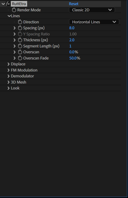
- Direction —
Horizontal Lines/Vertical Lines/Grid/Dots.Griddraws both families (they add together; occlusion applies within each family).Dotsplaces a dot lattice; dots displace vertically inAcross (Classic)mode, and along the full displacement vector (both axes) inRadial (From Center)/Image Normalmode. - Spacing (px) — distance between line centers (or dot rows).
- Y Spacing Ratio — only lives in
Grid(spacing multiplier of the vertical family) andDots(horizontal pitch multiplier); greyed out otherwise. - Thickness (px) — line width; in
Dotsmode this is the dot diameter. - Segment Length (px) (v0.8) — how many pixels apart the line is actually evaluated. Between two evaluation points the line is a straight segment: the displacement and the colour are interpolated, nothing is re-sampled and nothing is re-shaded. 1 px (default) is the classic behaviour, evaluated at every pixel, and is an exact bypass. Raise it and the relief turns faceted — plotter output, an oscilloscope trace, low-poly terrain. Whole pixels only, because the number is the pixel spacing of the break points. It means the same thing in both
Render Modes; in3D Meshit simply thins the vertex grid. It is also the cheapest speed control in the effect, since it cuts the per-sample work by roughly its own factor —4costs about a third of the sampling. ⚠ The wave and the demodulator get under-sampled along with everything else. At large valuesPath Waveand theDemodulatorare only evaluated at the break points, so a short wavelength turns angular or disappears between them. That is part of the look, not a defect — but if you want a smooth wave, keepSegment Lengthwell belowWavelength. ⚠ Greyed out inDots, which has its own lattice (SpacingandY Spacing Ratio) and no line to break up. It is also independent ofSignal Path: Radial, which runs on its own polar buffer at 1 px steps — this control thins the raster, not the chain. - Overscan (v0.5) — how far past the frame the raster keeps building lines, as a percentage of the frame. Default 0 %, and 20 % is usually plenty. Use it when a radial displacement pushes the edge lines out and empties the border: with overscan there is always another line waiting outside to be pulled in. Cost grows linearly — 20 % costs about 1.4×. It extends the raster across the lines (more lines), not along them. ⚠ There is no image outside the frame, so the extra lines sample the clamped border pixels and carry a smear of the edge — that is what
Overscan Fadeis for. - Overscan Fade (v0.5) — dims the lines resting outside the frame in proportion to how far out they are (100 % = the outermost line goes black). Default 50 %. Dead while
Overscanis 0.
Displace
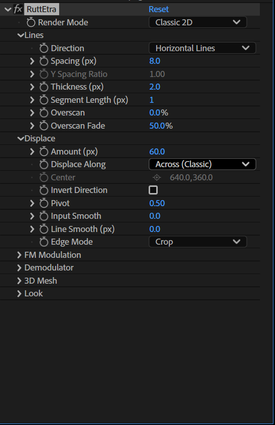
- Amount (px) — how far luminance pushes the line. 0 = flat raster (scan-line look with no relief).
- Displace Along (v0.2) — which way the luminance relief pushes:
Across (Classic)— perpendicular to the line, one global direction (the v0.1 behaviour and the faithful hardware look).Radial (From Center)— a Z-perspective: bright areas move away from Center, more the farther they are from it (the center itself is anchored). WithInvert Directionthe image contracts toward Center — nothing ever leaves the frame.Image Normal— each point moves along the image's own luminance gradient: lines bulge around bright blobs, each blob around its own rim.Pivotplays no role here (greyed out); raiseInput Smoothto steady the gradient on noisy footage.
- Center (v0.2) — the anchor point shared by
Radial (From Center)displacement andRadial (Rings)phase geometry; greyed out while neither is active. Like every AE point parameter it lives in the layer's own coordinate space — precompose if you want it in comp space. - Invert Direction — bright areas push the other way.
- Pivot — the luminance that stays put (0.5 = mid-grey anchored; 0 = black anchored, everything pushes one way). Not used by
Image Normal. - Input Smooth — softens the sampled image before displacement (0–5, like mip levels: each step roughly doubles the blur). Smooths the relief so lines don't jitter on noisy footage. 0 = exact bypass of the blur. It blurs the whole frame in both directions, so it smooths across the lines as well as along them — that is what keeps neighbouring lines coherent with each other.
- Line Smooth (px) (v0.8) — smooths what each line samples along its own length (0–64 px, default 0 = exact bypass). Its sibling above blurs the entire frame; this one only filters the thin strip each line actually reads, which costs almost nothing even at large radii — at
Spacing 8the lines sample about an eighth of the picture. Reach for it first when a single line is jittery along its run and you only want that steadied. ⚠ It is a companion toInput Smooth, not a replacement. It cannot smooth the incoherence between neighbouring lines, because it never looks sideways — only the cross direction ofInput Smoothdoes that. If the relief looks like independent noisy wires rather than one surface, you needInput Smooth(or both). It filters the sampled colour as well as the luminance, so the line's colour steadies with its shape, and it runs forwards and then backwards so it has no group delay: the smoothed relief stays exactly where the sharp one was, no matter how far you push it. Scales with resolution like every other px control. It does not touch theDemodulator's internal sampling — that chain has its ownDemod Smooth. - Edge Mode (v0.2) — what happens to a line pushed past the frame edge:
Crop— it slides off, like the raster running off the real CRT (default, the v0.1 behaviour).Wrap— what leaves at the bottom re-enters at the top (the authentic "vertical hold" TV roll). Note that an animated line teleports across the frame at the moment it wraps.Fold— the line bounces back off the edge; animation stays continuous.Compress— a soft limiter: the line approaches the edge asymptotically and never leaves; the raster visibly squashes near the edges like an overdriven signal.- ☠ Painting (occlusion) order never changes: a wrapped or folded segment keeps its own line's depth, so a line re-entering from the top may cover, or be covered, exactly as its original position dictates. The transform maps the line's center; the anti-aliased fringe still crops at the frame boundary. In
Dotsmode the transform applies per axis.
FM Modulation
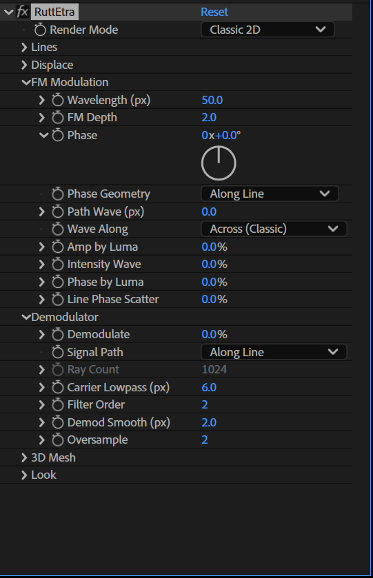
☠ This whole group is dead while Path Wave = 0 and Intensity Wave = 0 — by design, bit-exactly: the phase accumulator is not even evaluated. That includes the v0.2 members: Phase Geometry, Phase by Luma and Line Phase Scatter do nothing until one of the waves rises (and Amp by Luma and the v0.3 Wave Along need Path Wave > 0). Raise either wave to bring the group to life.
- Wavelength (px) — carrier wavelength on black (luma 0). In
Radial (Rings)geometry this is the ring spacing. - FM Depth — how strongly luminance raises the frequency:
f = (1 + depth · luma) / wavelength. At depth 2, pure white oscillates 3× faster than black. 0 = unmodulated carrier. Only meaningful inAlong Linegeometry — greyed out onRadial (Rings)(a ring field has no running accumulator; couple the image throughPhase by Luma/Amp by Lumainstead). - Phase — starting phase; animate it to make the waves travel. ☠ In
Radial (Rings)geometry, increasingPhasemoves the rings outward (v0.3 fixed the sign; in v0.2 the same animation ran inward). One full turn = one carrier cycle. No hidden time dependence. - Phase Geometry (v0.2) — where the carrier phase comes from:
Along Line— the classic v0.1 accumulator: phase runs along each line, luminance modulates its frequency. AnimatingPhasesweeps the pattern along the lines — this is what can read as "wind from the side".Radial (Rings)— the phase is a field: concentric rings aroundCenter. Every line shows the same ring pattern where it crosses it; animatingPhasemakes the rings travel outward (v0.3; measured) — waves organized from a point, no sweep direction. Pair it withWave Along: Radial (Breathe)to get rings that actually breathe rather than crests that slide along the lines.
- Path Wave (px) — the line's path oscillates up/down by this amplitude, denser where the image is bright.
Wave Along (v0.3) — which way the Path Wave pushes. This is the answer to "the waves always travel sideways": with a radial
Phase Geometrythe rings sat still but the crests slid along the lines, because the displacement itself was always across them.☠ Known artifact, by design (both radial modes): on the axis through
Centerthat runs parallel to the lines, the radial direction points along the line, so the wave's visible (across) component dies there — a horizontal-line raster shows a calm band through the Center. MoveCenteroff that band, or useGridso the other family covers it.Wave Alongis independent ofDisplace Along(that one steers the luminance relief, this one the wave); combine them freely. Like the rest of the FM group it is never greyed out — it simply does nothing whilePath Waveis 0.Across (Classic)— the v0.1/v0.2 behaviour, bit for bit: the line waves perpendicular to itself (inDots: vertically).Radial (Breathe)— the wave pushes along the(point − Center)direction, at constant amplitude everywhere. AnimatePhasewithPhase Geometry: Radial (Rings)and the rings breathe in and out of the Center instead of drifting sideways. This is the recipe the flag test was missing.Radial (Perspective)— the same direction, but the amplitude grows with the distance fromCenterand dies out around it. Reads as more depth: near the Center the surface is calm, out at the edges it swells. (Same(p − C) / half-diagonalscale asDisplace Along: Radial.)
- Amp by Luma (v0.2) — the image gates the Path Wave's amplitude: at 100 % dark areas stay straight and bright areas carry the full wave. The cheapest way to make the wave belong to the picture.
- Intensity Wave — the line's brightness carries the wave: 100 % stripes the line down to black in the wave troughs, denser where bright. Combine both for a wobbling and striped analog-signal look.
- Phase by Luma (v0.2) — luminance is added directly into the phase, in place (it does not accumulate or drift downstream): a bright patch kinks the wave exactly at its own rim. 100 % = pure white shifts a full cycle. Affects both waves.
- Line Phase Scatter (v0.2) — each line starts from its own deterministic phase offset (up to a full turn at 100 %). Breaks the line-to-line coherence — the "textile sheet" becomes a bundle of independent signals. Deterministic: the same frame renders identically every time.
Demodulator (v0.6)
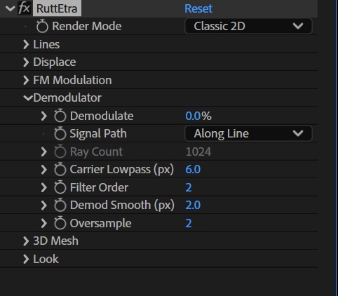
The chain that gives the analog artifact. It runs along each line (a row for Horizontal, a column for Vertical, both families for Grid, the dot row for Dots), in four steps:
- Modulate — the luminance is turned into a frequency on a carrier, exactly the rule the FM group already uses:
Wavelengthis the carrier length,FM Depthhow hard luminance pushes the frequency. (No new "carrier" slider: the group above is the carrier. WithFM Depth 0there is nothing to demodulate and the whole chain is skipped.) - Lowpass the carrier —
Carrier Lowpasscuts the modulated carrier. ☠ This is the whole trick: it is not a blur on the picture. A blur is a weighted average and can never leave the image's own value range; filtering the carrier corrupts the phase, and the error comes back through the frequency non-linearly — as overshoot past white and past black. - Demodulate — the value is read back from the filtered phase.
- Smooth —
Demod Smoothsmooths the recovered signal.
The recovered value drives the displacement only (the luminance relief and Amp by Luma). Colour, Glow, Phase by Luma and the drawing phase keep reading the untouched image, so Channel Shift and Spectral are unaffected. One exception worth knowing: under Displace Along: Image Normal the relief comes from a gradient field of the whole picture rather than from the sampled luminance, so there the chain only acts through Amp by Luma.
Every control here is one function:
- Signal Path (v0.7) — where the chain runs.
Along Line(default) — along the raster line, filtered forward only. The filter lags, so the ringing trails in the scan direction: left to right for horizontal lines, top to bottom for vertical ones.Along Line (Symmetric)— the same path, but every filter runs forward and backward. The filter's net phase is zero, so the ringing sits symmetrically on both sides of an edge and the directional drag is gone. Side effect: the filter is effectively twice the order, so the sameCarrier Lowpassbites harder.Radial (from Center)— the chain runs outward along rays fromCenter, on an internal polar buffer. The artifact radiates from the centre instead of sweeping sideways. On a radially symmetric image the result depends only on the radius.
- Ray Count (v0.7) — how many rays the radial chain uses, 64–4096. Live only in
Radial. Neighbouring rays are2π · R / Ray Countpixels apart at the outer edge (R = the distance fromCenterto the far corner), so at 1024 rays and a 1100 px radius they are about 7 px apart out there — smooth for rings, but drop to 256 if you need the speed and raise it if a hard angular edge turns into spokes. Cost scales with it. - Demodulate — how much of the demodulated signal takes over, 0–100 %. 0 % (default) is an exact no-op: the entire chain is skipped and the render is bit for bit the v0.5 one. 100 % is "fully demodulated". The other four controls do nothing while this is 0 — they are not greyed out (the same convention as the FM group).
- Carrier Lowpass (px) — how hard the carrier is cut, as a smoothing length in pixels. This is where the artifact comes from. 0 px = no filter, and then the chain is an exact identity (demodulating gives the image back). The useful range is roughly the carrier length: with
Wavelength 8, values of 2–16 px go from a light wobble to heavy ringing. - Filter Order — how steep that cut is, 1–4. Order 1 barely rings; each step up deepens the overshoot and lengthens the ringing tail.
- Demod Smooth (px) — how smooth the recovered signal is. This is the "line-like vs. painted" control: 0 px keeps every hard wave-line the demodulator produces, 24 px melts them into soft painted shapes.
- Oversample — internal samples per pixel, 1–8. Short carriers need it: the phase must advance less than half a turn per sample or the recovery breaks up into noise. Rule of thumb:
Wavelengthabove2 · (1 + FM Depth)px is safe at 1; halve that requirement per doubling ofOversample. Costs time linearly.
The whole group is greyed out in 3D Mesh mode — the chain is a Classic 2D feature.
3D Mesh (v0.4)
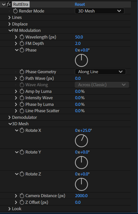
The whole group is greyed out while Render Mode is Classic 2D.
- Render Mode —
Classic 2D(default) /3D Mesh.Classic 2Dis the v0.1–v0.3 renderer, bit for bit. None of the mesh code runs, and the five controls below are not even read.3D Meshrebuilds the raster as a real surface: each sample point becomes a vertex at its rest position, the luminance relief and the Path Wave both push it in Z (toward the viewer for bright areas), neighbouring vertices are joined by anti-aliased segments, and a z-buffer decides what hides what. Line thickness and dot diameter scale with distance, so near parts of the surface are visibly thicker. A line never hides itself: each line is rasterised as one surface before it meets the z-buffer, so its own segments cannot cut notches into it (v0.9.1).
- Rotate X / Y / Z — rotation around
Center(on the base plane), applied X first, then Y, then Z. PositiveRotate Xtips the top away from you (bright areas rise on screen — the classic Rutt/Etra terrain, which is why the default is 25°); positiveRotate Yswings the right-hand side away; positiveRotate Zturns clockwise on screen. - Camera Distance (px) — how far the camera sits in front of the base plane. Smaller = stronger perspective. At the default 2000 px a HD layer reads like a normal lens. Anything that would end up closer to the camera than 1/1000 of this distance is clipped away (see Notes).
- Z Offset (px) — moves the whole surface along Z: positive = toward the camera (the terrain grows), negative = away.
☠ What is dead in 3D Mesh mode (greyed out): Displace Along, Wave Along and Edge Mode. All three are 2D-raster concepts — the displacement now goes into Z, and the camera replaces them. Center is the opposite: in mesh mode it is always live, because it is both the rotation pivot and the projection centre. Pivot is live too, even on Image Normal.
⚠ Performance: 3D Mesh is the slower path — one vertex per sampled pixel, plus segment rasterisation with a z-buffer. It is opt-in for exactly this reason. Increase Spacing (fewer lines) if a 4K comp gets sluggish.
Lighting (v1.0)
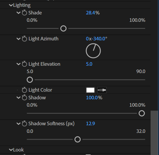
The whole group is greyed out while Render Mode is Classic 2D; it lights the mesh only. One directional light, Lambert shading, and an optional self-shadow.
The model. Every vertex gets a normal from the surface around it: the direction along its own line and the direction across to the neighbouring lines (in Dots, the row and column neighbours; in Grid, each family on its own). The normal is computed after Rotate X / Y / Z, so the light is fixed to the camera, not to the terrain — turn the mesh and the lit side moves. The light is a direction only (no position, no falloff): lit = max(0, n · L), and each colour channel of the line is multiplied by
k = 1 − Shade · (1 − lit · shadowK · LightColor)so Shade mixes between the self-luminous line (k = 1) and the fully shaded one, where the side facing away from the light goes black; 1 − Shade is the ambient share. The shading multiplies the line colour after Depth Fade and the Color Source, so Flat (Tint) does not cancel it — a constant base colour is exactly what makes the geometry the only thing left to read, and Flat (Tint) + Shade is the cleanest lit relief. Original, Mono and Spectral multiply their own colour with the shading.
- Shade — the amount of shading, 0–100 %. 0 = exact bypass: none of the lighting code runs, no normals, no depth map, and the render is bit for bit the unlit one. 100 % = the far side is black.
- Light Azimuth — where the light comes from, around the frame. The dial points at the light: 0° = from the top of the frame (the default), 90° from the right, 180° from below, 270° from the left, clockwise like the dial.
- Light Elevation — how high the light stands over the picture plane, 5–90°. 45° (default) gives shading and shadows of equal weight; 90° is a headlight from the camera: every flat area is lit the same, only slopes darken, and nothing can be in shadow (the
Shadowcontrol has nothing to do — it is not greyed out, it simply finds nothing). - Light Color — the colour of the light. It multiplies inside the formula, so it colours what the light reaches and leaves the ambient share alone: a warm light on a cool
Tintshades in two tones. Black light withShade100 % is a black line. - Shadow — self-shadowing, 0–100 %. 0 = the depth map is not built. Above 0 the mesh is rendered once more from the light's point of view (orthographic, one map pixel per picture pixel, every line at its own thickness) into a depth map, and every vertex asks whether something sits between it and the light; the answer scales the light term (
shadowK). A raised plateau lit from the top at 45° throws a shadow exactly as long as it is high. Because the lookup is per vertex, a thick line is lit or shaded as a whole across its width. A line never shadows itself, and a vertex with alpha 0 (seeAlpha Affects) casts nothing. - Shadow Softness (px) — the shadow edge is filtered over a 5×5 grid spanning this many pixels around each lookup (a fixed-cost soft shadow): 0 = hard, 2 (default) = a slightly softened edge, 32 = broad penumbra. It also hides the comb pattern that thin lines can leave in a shadow.
☠ What lighting is not: there is no specular highlight, no point or spot light, and the light does not come from the comp's light layers — one directional light, internal to the effect. Depth Fade is not a shadow either (see Look).
⚠ Performance: Shade alone adds roughly a third to the mesh time (the normals and one extra pass of vertex bookkeeping); Shadow renders the mesh a second time into the depth map and costs roughly another mesh — about 2.3× the mesh time in all, independent of Shadow Softness. Both are exactly free at 0.
Look
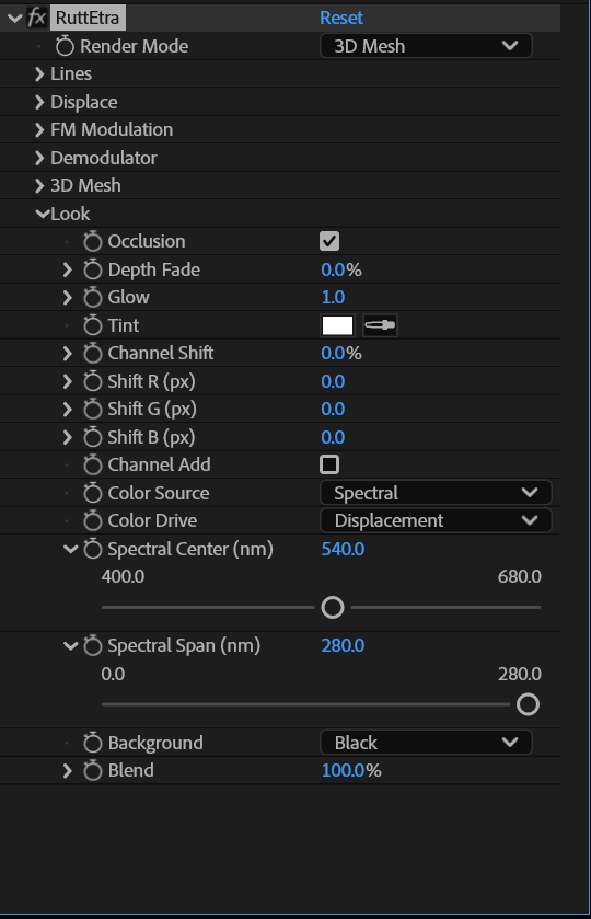
- Occlusion — on (default): the classic relief, nearer lines cover farther ones. Off: additive lines that shine through each other (the additive look). ☠ This control alone decides how the lines combine with each other —
Backgrounddoes not. With Occlusion off, wherever two different lines overlap their colours are added (up to a clamp of 8× white) and the coverage is the union; with it on, the nearer line covers the farther one. A line never adds to itself (v0.9.1). The same holds in3D Mesh: off is additive with no depth test at all, on is the z-buffer. Since the output is straight alpha, an additive overlap can be brighter than its alpha allows — over another layer in the comp such points overshoot; switch Occlusion on if that is unwanted. (A separate "normal, in painting order" blend for the Occlusion-off case is a possible later addition; today off means additive.) - Depth Fade — lines displaced far from their rest position darken (cheap depth cue). In
3D Meshit reads the Z displacement, so it is a depth signal computed from how far a point was pushed — not a shadow; the shadow belongs to the Lighting group, and the two multiply independently. - Glow — bright parts of the image make their lines glow brighter (multiplies by
1 + luma · Glow). 0 = exact bypass. ☠ Greyed out underColor Source: Flat (Tint), where it is dropped from the formula outright — otherwise luminance would still modulate the lines through their brightness. - Tint — multiplies the line color.
- Channel Shift (v0.5) — chromatic aberration driven by the displacement: red is drawn at
(1 + shift)of the displacement and blue at(1 − shift), green stays put. Flat areas stay clean; the colour splits where the relief is strongest. In3D Meshmode the Z displacement is what scales, so the split arrives through the perspective — and the depth used for occlusion is always green's, so the split never breaks the hiding. - Shift R / G / B (px) (v0.7) — an absolute offset per colour channel, in pixels, −64 … +64. This is a different function from
Channel Shift: the percentage above scales with the relief (dispersion that grows with the terrain), these move each channel by the same amount everywhere (a flat registration error). They work together and neither replaces the other. The offset acts across the lines (and on the dot's vertical position); in3D Meshmode it is added to the Z displacement, with the occlusion depth still taken from green. - Channel Add (v0.7) — where the three channel copies overlap, add them instead of letting the nearer one cover the further one. This is the classic additive RGB split. Two things to know: it does nothing unless at least one channel is actually offset (by
Channel Shiftor by the pixel sliders), and it is aClassic 2Dfeature — in3D Meshmode the z-buffer decides who covers whom. It is off by default so that existingChannel Shiftsetups render exactly as before; turn it on for the aberration look. - Color Source — where the line's colour comes from:
Original Colors— lines are painted with the image's own colors.Mono (Tint)— lines carry luminance × Tint: set Tint to green or white for the classic monochrome monitor look.Flat (Tint)(v0.3) — the line colour is constant Tint; the image does not modulate it at all. The most technical, plotter-like look. Two things still shade the line, on purpose, because neither reads the image:Intensity Wave(phase-driven) andDepth Fade(geometry-driven).Glowis dead here and greyed out. ☠ Flat does not make the output image-independent — the geometry (the relief,Amp by Luma,Phase by Luma) still comes from luminance; only the colour is fixed.Spectral(v0.5) — the line is coloured by the wavelength its displacement maps to. This is a real spectrum, not a hue wheel: the CIE 1931 2° colour matching functions give XYZ, which is converted to sRGB and desaturated toward white where the colour falls outside the gamut. The consequence you can see: a hue wheel passes through magenta, and this does not — magenta is a mixture of the two ends of the spectrum and has no wavelength of its own.Glowstays alive here (unlike underFlat): the colour comes from the displacement, the brightness may still come from the image.Tintstill multiplies, so a white Tint gives the pure spectrum.
- Color Drive (v0.7) — what the spectrum reads. Greyed out unless
Color SourceisSpectral.Displacement(default) — the v0.5/v0.6 behaviour: the colour follows how far the line was pushed from its rest position. With the classicAcrossdisplacement that is close to a brightness map anyway; withDisplace Along: RadialorImage Normalit colours the deviation instead, andPath Wavesweeps the band as well.Luma (Thermal)— the colour is driven by the brightness of the sample: dark maps to the low end of the band and bright to the high end, like a thermal camera. It reads the untouched image, not the demodulated signal, so the Demodulator changes the geometry while the colour stays a clean heat map. ⚠ This is a spatial mapping, not a temporal one — the effect has no notion of motion between frames.
- Spectral Center (nm) / Spectral Span (nm) (v0.5) — the band the displacement sweeps:
Center ± Span/2. Both greyed out unlessColor SourceisSpectral. ⚠ The usable range is 400–680 nm and the colour holds at those limits. That is where the analytic fit tracks the CIE data; beyond it the eye's response falls under about 1 % of peak and the fit drifts (at 740 nm it would render green). 400–680 covers the whole visible rainbow, violet through deep red. - Alpha Affects (v0.9) — what the layer's own alpha does to the lines. The alpha is sampled at the same point and along the same path as the colour (through
Input Smooth,Line SmoothandSegment Lengthalike), and there is no second slider: the alpha is the amount, 0–1.
| setting | line coverage | line thickness / dot radius |
|---|---|---|
Off (default) |
unchanged | unchanged — the alpha is not read at all |
Opacity |
× alpha | unchanged |
Thickness |
unchanged | × alpha — a line tapers, a dot shrinks, both to nothing at alpha 0 |
Both |
× alpha | × alpha |
In Thickness a line thinner than a quarter pixel does not thin further but fades in proportion instead, so the taper runs continuously into zero rather than stopping at a hairline; at alpha 0 nothing is drawn at all. In 3D Mesh the alpha is taken at each vertex and averaged over the segment, like the colour; it scales the projected thickness, and a fading line stops writing depth as its coverage falls, so it does not cut a hole into the line behind it. The Demodulator is untouched — the chain carries luminance, not alpha. On an opaque layer all three settings render exactly as Off. ⚠ With Background: Black the output keeps the layer's alpha, so in Opacity the area around a cut-out stays transparent, not black — a black frame, if wanted, is a solid behind the layer. Amount is deliberately not scaled: a line that thins or fades to nothing does not need its relief flattened as well.
- Background — what sits behind the lines:
Black(classic, default),Original(the source image shows through the gaps),Transparent(alpha holes — comp over anything). It only chooses what goes under the lines; how the lines blend with each other — added, or nearer covering farther — isOcclusion's decision, in every Background. - Blend — mix with the untouched source. 0 % = bit-exact passthrough.
Notes
- Resolution / preview: all pixel-based parameters scale with the preview downsample, so Half/Quarter preview shows the same composition.
- 8/16/32 bpc supported; alpha is treated straight. With
Alpha Affectsoff the alpha is never read by the raster; on, it is sampled straight, not premultiplied — the colour is never multiplied by it, the alpha is a separate factor on the coverage and/or the thickness. - The line layer is clamped to a generous HDR ceiling (8.0) before compositing.
- With
Background: Transparentthe gaps have alpha 0 — put anything behind the layer. - Grid families combine additively even with Occlusion on (occlusion acts within each family). In 3D Mesh mode this is different on purpose: the grid is one single mesh sharing one z-buffer, so the two families occlude each other properly.
- 3D Mesh, near clipping: a vertex that ends up closer to the camera than
Camera Distance / 1000is dropped, and any segment touching it goes with it. With a very smallCamera Distanceor a very largeAmountyou can therefore see parts of the surface disappear — that is the near plane, not a bug. - 3D Mesh, edge of the surface: the mesh is built from the same set of lines as the 2D raster, i.e. one line beyond each edge of the frame. Under a strong rotation you may see the border of the surface itself.
- 3D Mesh with
Occlusionoff: the lines are added together with no depth test at all (a pure additive blend). Depth then affects only the perspective scale, never who covers whom. - 3D Mesh and
Depth Fade: it reads the Z displacement, so it keeps its meaning — the further a point is pushed out of the base plane, the darker it gets. - Demodulator and the FM group: they share
Wavelength,FM Depth,PhaseandLine Phase Scatter— one carrier, used by both. ChangingWavelengthfor the chain therefore also changes the Path/Intensity waves if those are on. AnimatingPhasedrifts the artifact along with the waves, which is usually what you want. - Demodulator, safety rail: the recovered value is clamped to a generous −0.5 … 1.5 range. The overshoot is the effect, so it is not clamped to 0…1 — but the rail keeps an extreme setting from throwing a line halfway across the frame.
- Demodulator, cost: the chain runs once per line before it is drawn, so the cost is roughly
Oversampleextra samples per pixel of line. It is off entirely atDemodulate 0 %. InRadialmode the cost is set byRay Count × radiusinstead, independent of the line spacing. - ⚡
Input Smoothused to be the most expensive control in the effect — in v0.7 it cost more than the entire raster at 4K. v0.8 made it about six times faster, and its cost no longer depends on how far you push it: the blur now carries a running window total, soInput Smooth 5costs the same asInput Smooth 2. It is still the heaviest single control, just no longer by a wide margin. If you need something cheaper still, two routes:Line Smooth(v0.8) smooths along the lines almost for free, though it cannot replace the cross direction; or a GPU-accelerated blur above this effect on the same layer —Fast Box BlurorGaussian Blurplaced before RuttEtra in the effect list feeds its blurred result straight into us (no precomp needed). One real difference with the external route:Input Smoothsoftens only what the lines sample, soBackground: OriginalandBlendstill show the sharp image, while an external blur softens those too. - What costs what (measured at 4K on the v0.8 core, relative to the default horizontal raster):
Grid≈ 2.0×,Dots≈ 0.44×,3D Mesh≈ 2.9×,3D Mesh+Grid≈ 6.8×,Input Smooth 2≈ 1.5× andInput Smooth 5≈ 2.0×,Line Smooth 12≈ 1.2×,DemodulateatOversample 2≈ 2.5×, atOversample 8≈ 6.1×,Spacing 2≈ 2.6×,Channel Shift≈ 1.5×.OverscanandSpectralare nearly free. (v1.0, measured against the mesh itself:Shade≈ 1.3× the mesh time,Shade+Shadow≈ 2.3×, whatever theShadow Softness; both exactly free at 0.) ⚡Segment Lengthis the one control that makes things faster:4costs 0.77× and16costs 0.72× of the default. It pays off most in3D Mesh, where the per-vertex work is the expensive part —3D MeshwithSegment Length 4runs about 2× faster than mesh at 1, and at16about 3×. It helps theDemodulatortoo, since the chain then runs on the thinned lattice:Oversample 2withSegment Length 4is about 2.3× faster than the same setting at 1. ⚠ The default raster is also about 1.4× faster than v0.7 on its own, from the source buffer dropping its unused alpha lane.
Version history
- v1.0 —
Lighting. One directional, coloured light on the3D Mesh, with self-shadowing. Each vertex takes a normal from its own line and the neighbouring lines (row and column neighbours inDots), computed after the rotation so the light stays fixed to the camera; the line colour is multiplied by a Lambert term,Shademixing between the self-luminous line and the fully shaded one,Light Colorcolouring only what the light reaches.Shadowrenders the mesh once more from the light's point of view into a depth map and asks per vertex what stands between it and the light;Shadow Softnessfilters the edge over a fixed 5×5 grid. The light comes from the top of the frame at 45° by default, the azimuth dial points at the light, elevation 90° is a headlight.Flat (Tint)does not cancel the shading — it is the cleanest base for it.Shade0 (the default) runs none of it and renders bit for bit as before;Shadow0 never builds the map. New group after3D Mesh, greyed out inClassic 2D; nothing else moved. - v0.9.1 — the mesh raster no longer hides itself. In
3D MeshwithOcclusionon, lines broke up into dark notches wherever they bent: a line is drawn as short segments, the end of one segment wrote its depth into the z-buffer, and the next segment lost the depth test against it at the same pixels. Each line is now rasterised as one surface — every pixel keeps the strongest coverage its segments give it — and meets the z-buffer once, so a line never occludes itself while the painting order between lines is unchanged. The same held between the three channels of one line underChannel Shift— green wrote its depth and red and blue then lost the test against it, pixel by pixel — so green's depth is now written only after all three channels of the line are drawn. Dots andClassic 2Drender exactly as before; the mesh line renders are the intended ones now. No new controls. - v0.9 —
Alpha Affects. The lines can now follow the layer's own alpha:Opacityfades them with it,Thicknesstapers them (and shrinks the dots) to nothing where the alpha reaches zero,Bothdoes both. The alpha travels the same path as the colour —Input Smoothblurs it on its own plane with the same filter,Line Smoothsmooths it along the line,Segment Lengthinterpolates it between the knots — and in3D Meshit is averaged over each segment like the colour. Below a quarter-pixel line width the taper turns into a fade so it ends continuously. The default isOff, where the alpha plane is not even built, and an opaque layer renders identically in every setting. The Look group gains one popup, in front ofBackground; nothing else moved. - v0.8 — the speed round, and two controls that are speed and look at once. The plugin had become slow to respond, and the measurement named
Input Smooth: at 4K it cost more than the whole raster. Its blur was doing two things badly — walking columns in a way that missed cache on almost every sample, and re-adding the whole window at every pixel — and both are fixed. It is now about six times faster, and its cost is independent of the setting, so 5 costs what 2 costs. The source buffer also dropped an alpha lane nothing ever read, which makes the default raster about 1.4× faster on its own. Nothing about the output changed except in two measured places, where the new summation order shifts the last bits of a blurred render. On top of that, two new controls.Segment Length (px)evaluates the line every N pixels and draws a straight segment in between — a plotter / low-poly look, and the only control in the effect that makes rendering faster (about 2–3× in3D Mesh).Line Smooth (px)smooths what each line samples along its own length, almost for free, as a companion toInput Smoothrather than a replacement — it cannot touch the incoherence between lines. Both are exact no-ops at their defaults. - v0.7 — aiming the chain, and colour by channel. The demodulator no longer has to read left to right:
Signal PathaddsAlong Line (Symmetric), which filters back and forth so the ringing sits evenly on both sides of an edge instead of trailing one way, andRadial (from Center), which runs the chain outward along rays on an internal polar buffer so the artifact radiates fromCenter— withRay Counttrading its angular resolution against speed. On a radially symmetric image the radial chain's output depends only on the radius, which is what the offline suite measures.Shift R / G / B (px)add an absolute per-channel offset in pixels alongside the existing proportionalChannel Shift, andChannel Addmakes overlapping channels add instead of cover — off by default, so older setups are untouched. AndColor Drivechooses what theSpectralpalette reads: the displacement as before, orLuma (Thermal)for a heat-map reading of brightness. All seven controls are bit-exact no-ops at their defaults. - v0.6 — the Demodulator: the line's luminance is transmitted as a frequency on the existing FM carrier, the modulated carrier is lowpassed, and the value is demodulated back out of the filtered phase. What the filter cannot follow returns as overshoot and ringing in the terrain — the analog artifact. It is deliberately not a blur: a blur is a weighted average and can never leave the image's own value range, while this chain overshoots past both ends (the offline suite measures exactly that). Five controls, one function each:
Demodulate(how much of it is used),Carrier Lowpass(how hard the carrier is cut — the source of the artifact),Filter Order(how steep that cut is),Demod Smooth(line-like ↔ painted) andOversample(internal sample density, the Nyquist guard). WithCarrier Lowpassat 0 the chain is an exact identity; withDemodulateat 0 — the default — it is skipped entirely and every older project renders bit for bit as before.Classic 2Donly; greyed out in mesh mode. - v0.5 — look development and room to breathe.
Overscanlets the raster keep building lines past the frame, so a radial displacement no longer runs out of canvas — it just pulls more in from outside; the cost is linear (about 1.4× at 20 %) because it extends across the lines, not along them, andOverscan Fadehides the smeared border pixels those outside lines necessarily carry.Channel Shiftsplits red and blue apart in proportion to the displacement — chromatic aberration that grows with the terrain, and in mesh mode it rides the perspective while occlusion still follows green alone. AndColor Source: Spectralcolours the line by the wavelength its displacement maps to, through the real CIE 1931 colour matching functions rather than a hue wheel — the visible difference being that a hue wheel passes through magenta and a spectrum never can. All three are bit-exact no-ops at their defaults. - v0.4 — the mesh round, and the real answer to what the flag test proved missing:
Render Mode: 3D Meshlifts the raster into space. Every sample point becomes a vertex, the luminance relief and the Path Wave both go into Z, an internal transform (Rotate X/Y/ZaroundCenter, thenZ Offset) and a perspective camera (Camera Distance) project it, and the surface is drawn as anti-aliased segments resolved by a z-buffer — with thickness scaling by distance. With a radialPhase Geometrythe terrain now genuinely breathes in and out ofCenterinstead of sliding sideways. In mesh mode the sampling happens at the rest position, so there is no probe and no inverse sampling: the mesh path is more exact than the 2D one, not less.Displace Along,Wave AlongandEdge Modeare dead there and greyed out;CenterandPivotare always live.Classic 2Dis the default, and the entire mesh branch is skipped there — every v0.1–v0.3 project renders bit for bit as before. - v0.3 — aimed at what the flag test proved missing:
Wave Along(Across / Radial Breathe / Radial Perspective) turns the Path Wave's displacement radial, so an animatedPhasebreathes in and out ofCenterinstead of sliding along the lines; the radial ring field'sPhasesign is reversed so that increasingPhasenow moves the rings outward (this is the one v0.3 change that alters an existing setup — it needsPhase Geometry: Radial (Rings), and it makes the v0.2 Help's "rings travel outward" claim true rather than aspirational); andColor Source: Flat (Tint)paints the raster in one constant colour.Wave AlongandFlat (Tint)are bit-exact no-ops at their defaults. - v0.2 — the anti-flag toolkit:
Displace Along(Across / Radial from Center / Image Normal), sharedCenter,Edge Mode(Crop / Wrap / Fold / Compress),Phase Geometry(Along Line / Radial rings),Amp by Luma,Phase by Luma,Line Phase Scatter. All new parameters are bit-exact no-ops at their defaults — v0.1 projects render identically. - v0.1 — first release: line/grid/dot relief, FM group (Path Wave + Intensity Wave on a shared, luma-driven phase), Occlusion / additive, Depth Fade, Glow, Tint, Mono mode, Background, Blend.
Questions & answers
What does "FM" mean here, and why do the waves get denser on bright areas?
A carrier wave runs along every line, and its only property is Wavelength — the carrier length on black. The picture does not change how tall that wave is (that would be amplitude modulation); it changes how fast the phase turns: per pixel the phase advances by 2π · (1 + FM Depth · luma) / Wavelength. On black the bracket is 1, so you get the wavelength you dialled; on white at FM Depth 2 it is 3, so the wave is a third as long there. Brighter = higher frequency = denser wave is the rule everywhere in the effect, and FM Depth 0 means the picture never touches the carrier. Because the phase accumulates, a bright patch also shifts everything downstream of it along the line — that is why the pattern seems to stream out of highlights; Phase by Luma is the opposite, it kinks the wave in place at the patch's own rim. Two controls ride on the one phase: Path Wave (the wave as position) and Intensity Wave (the same wave as brightness), so the stripes always sit on the crests. See FM in ten minutes.
A whole group of controls does nothing. Are they broken?
No — three groups are inert by design until one switch wakes them, bit-exactly. The FM Modulation group is dead while Path Wave = 0 and Intensity Wave = 0: Phase Geometry, Phase by Luma, Line Phase Scatter, Amp by Luma and Wave Along all wait for a wave. The Demodulator is skipped entirely at Demodulate 0 % (and has nothing to demodulate at FM Depth 0). The 3D Mesh group is grey in Classic 2D — and in 3D Mesh it is Displace Along, Wave Along and Edge Mode that go grey instead, because the camera does their job. Smaller cases: Glow is dropped under Flat (Tint), Center is grey while neither radial mode is active, Overscan Fade is dead at Overscan 0, Segment Length is grey in Dots. Raise the wave, the Demodulate mix or the mode and the group comes to life. See FM Modulation, Demodulator and 3D Mesh.
The waves sweep sideways like a flag. How do I make them belong to the picture?
Plain FM reads as one sheet waving sideways because the phase runs along every line in the same direction. Four controls pin it to the image, and they stack. Amp by Luma — dark areas stay straight, bright areas carry the full wave (the cheapest fix). Phase by Luma — bright patches kink the wave in place. Line Phase Scatter — every line gets its own starting phase, so the textile sheet becomes a bundle of independent oscilloscope traces. And to organise the waves around a point instead of a direction: Phase Geometry → Radial (Rings) plus Wave Along → Radial (Breathe), then animate Phase — the rings breathe in and out of Center instead of crests sliding along the lines (Radial (Perspective) makes the swell grow with distance from the centre). Known artifact of the radial modes: on the axis through Center that runs parallel to the lines the wave's visible component dies — move Center off that band or use Grid. If a radial displacement empties the frame edges, raise Overscan (20 % is plenty). See FM Modulation → Wave Along and recipe 6 in Quick start.
The lines jitter on noisy footage. Input Smooth or Line Smooth — which one, and what does it cost?
Two different jitters, two controls. If a single line shakes along its own run, Line Smooth (px) filters what each line samples along its length — nearly free at any radius, it filters colour with the luminance, and it runs forwards and backwards so nothing shifts sideways. If neighbouring lines disagree with each other — the relief looks like a bundle of independent noisy wires instead of one surface — that is Input Smooth's job: it blurs the whole frame in both directions, so it is the only one that smooths across the lines. They are companions, not alternatives. Since v0.8 Input Smooth costs the same whatever you set it to (measured 1.5–2× the default raster), and Line Smooth 12 about 1.2×. A third route: a GPU Fast Box Blur placed before RuttEtra in the effect list feeds its result straight in — the one difference being that Input Smooth softens only what the lines sample, so Background: Original stays sharp. See Displace → Input Smooth / Line Smooth and Notes.
How do I get the analog overshoot and ringing — and why does it look like torn noise sometimes?
That is the Demodulator (Classic 2D only): the line's luminance is transmitted as a frequency, the modulated carrier is lowpassed, and the value is read back from the damaged phase. Because the recovery divides rather than averages, the error comes back non-linearly — as overshoot past white and past black, then ringing. A blur can only flatten; this shoots past. Start by shortening the carrier: Wavelength 8 (the default 50 is meant for the Path Wave), Demodulate 100 %, then Carrier Lowpass 6 px, Filter Order 2, Demod Smooth 0, Oversample 2 for the hard, line-like artifact; Demod Smooth 24 px melts it into soft painted shapes. Carrier Lowpass 0 is an exact identity — show that first. Signal Path aims it: Along Line trails in the scan direction, Symmetric rings on both sides of an edge, Radial radiates from Center. Torn noise is Nyquist: the phase must advance less than half a turn per sample, so Wavelength > 2 · (1 + FM Depth) px at Oversample 1, and every doubling of Oversample halves that requirement — raise it, or lengthen Wavelength. Keep Segment Length well below Wavelength for the same reason. See The artifact, Nyquist and Demodulator.
How do I stand the relief up in real 3D, and keep a 4K comp responsive?
Render Mode → 3D Mesh: every sample point becomes a vertex, the luminance relief and the Path Wave go into Z, and an internal camera projects it with a z-buffer — near lines are drawn thicker and hide the ones behind. Rotate X (default 25°) tips the terrain, Rotate Y / Z turn it, Camera Distance sets the lens (smaller = stronger perspective), Z Offset moves it toward you. Combine with Radial (Rings) + Path Wave + animated Phase and the rings breathe out of Center in depth. Mesh costs about 2.9× the default raster, so the speed controls matter: Segment Length thins the vertex grid instead of removing lines — 4 runs about 2× faster, 16 about 3× — and Spacing removes lines. A vertex closer to the camera than Camera Distance ÷ 1000 is clipped (that is the near plane, not a bug), and under strong rotation you may see the border of the surface. See 3D Mesh and Notes.
With a transparent background, are the lines composited additively — or does the nearer line cover the farther one?
That is decided by Occlusion, not by Background. Occlusion off: the lines are added together wherever different lines overlap (colour sums, coverage unions), in Classic 2D and in 3D Mesh alike — the "shining wires" look. Occlusion on: the nearer line covers the farther one (in 2D the lower line, in 3D the z-buffer decides). Background only chooses what is placed under that result — black, the original picture, or nothing — so Transparent + Occlusion off is additive lines with a coverage alpha, and Transparent + Occlusion on is covering lines with the same alpha. Because the output is straight alpha, additive overlaps can carry more colour than their alpha, which reads as a brighter spot when the layer sits over something else; that is the additive look, not an error. Lighting works in both modes, since it scales each line's colour before the lines are combined. See Look → Occlusion and Look → Background.
How do I light the relief — and does Flat (Tint) cancel the shading?
Lighting → Shade (3D Mesh only). At 0 the lines are self-luminous, as they always were; raise it and each line takes its brightness from how its bit of surface faces the light — a slope toward the light is bright, the far side of a ridge is dark, 100 % makes that side black. The light comes from the top of the frame at 45° by default; Light Azimuth walks it around (the dial points at the light), Light Elevation 90° is a headlight, Light Color tints only what the light reaches. Shadow adds self-shadowing from a depth map rendered from the light's view — a plateau lit from the top at 45° throws a shadow as long as it is high — and Shadow Softness blurs its edge. No, Flat (Tint) does not cancel it: the colour source decides the base colour and the shading multiplies it afterwards, so a constant base is exactly the cleanest lit relief — the picture then contributes only the geometry. With Original the luminance and the shading multiply, which reads as a lit photograph. Depth Fade is not a shadow (it darkens by displacement) and the two stack. See Lighting and Look → Depth Fade.
I turned Shadow up and nothing changed. What has to be true for a shadow to appear?
Four things, in this order. Render Mode must be 3D Mesh — in Classic 2D the whole Lighting group is greyed out and not read. Shade must be above 0: it is the master amount of the group, and Shadow only scales the light term inside that mix, so at Shade 0 the depth map is not even built — Shadow 100 % over Shade 0 is the unlit render, bit for bit. Light Elevation must be below 90°: a headlight from the camera cannot put anything in shadow, because whatever the camera sees, the light sees too; at 45° a raised area throws a shadow exactly as long as it is high, and a lower light throws a longer one. And there has to be something to be shadowed: a smooth slope never shadows itself, a line never shadows itself, and a vertex with alpha 0 casts nothing — shadows appear where the relief stands up above what lies behind it in the light's direction, so raise Amount (px) or lower the light. Once the shadow is there, Shadow sets how dark it is (100 % = the light contributes nothing in the shadowed part; the ambient share 1 − Shade always remains), and Shadow Softness sets the edge — if thin lines leave a comb pattern in it, the default 2 px already hides that. See Lighting.
Green CRT, rainbow, thermal, RGB split — where do the colours come from?
Color Source decides. Mono (Tint) + a green or white Tint is the vintage monitor (raise Glow a little, add Depth Fade). Flat (Tint) is a constant colour, the plotter look — note the geometry still comes from the image, only the colour is fixed. Spectral colours the line by the wavelength its displacement maps to, through the real CIE colour matching functions — a true spectrum, so it never passes through magenta; Spectral Center / Span pick the band (usable 400–680 nm), and Color Drive → Luma (Thermal) drives it by brightness instead, cold to hot like a FLIR image. For the split: Channel Shift is dispersion that grows with the relief, Shift R / G / B (px) is a flat registration error everywhere — use both — and Channel Add makes overlapping channels add up instead of covering, the classic additive RGB split (it only does something once a channel is actually offset). See Look.
Lines, grid or dots — and what does each cost?
Direction picks the raster: Horizontal or Vertical Lines is the classic, Grid draws both families at once (they add together; occlusion applies within each family, and in 3D Mesh the two families occlude each other properly), Dots turns the image into a displaced dot lattice where Thickness is the dot diameter and Y Spacing Ratio the horizontal pitch. Measured at 4K against the default horizontal raster: Grid ≈ 2.0×, Dots ≈ 0.44×, 3D Mesh ≈ 2.9×, Mesh + Grid ≈ 6.8×, Spacing 2 ≈ 2.6×, Demodulate at Oversample 2 ≈ 2.5×; Overscan and Spectral are nearly free, and Segment Length is the one control that makes things faster (4 ≈ 0.77×). See Lines and the cost table in Notes.
How do I animate it — and make a loop that closes exactly?
Nothing moves by itself: animate Phase. One full turn is exactly one carrier cycle, so Phase keyframed 0° → 360° is a seamless loop; with Radial (Rings) the rings travel outward as Phase increases. Beyond the waves, everything is keyframable: Amount for the relief growing in, Center drifting across the frame, Rotate X/Y/Z in mesh. When a displaced line runs off the frame, Edge Mode decides its fate — Crop slides off (the CRT), Wrap re-enters from the other side (the "vertical hold" roll, but an animated line teleports at the moment it wraps), Fold bounces back and stays continuous, Compress squashes toward the edge like an overdriven signal. See FM Modulation → Phase and Displace → Edge Mode.
How do I put the lines over the original picture, or over anything else in the comp?
Background decides what sits behind the lines. Black is the classic monitor look; Original keeps the source image visible in the gaps between the lines; Transparent cuts real alpha holes (the gaps have alpha 0), so the lines can be composited over any layer underneath, glowed or blended on their own. Blend mixes the whole result back toward the untouched source — 0 % is a bit-exact passthrough. See Look → Background.
My layer has transparency — a mask, a feathered edge — but the lines run right across the transparent area. Can they fade with the alpha?
Yes — Alpha Affects in the Look group (v0.9). By default the plugin draws every line from the luminance and never reads the alpha, so a transparent area (luma 0) gives flat lines that a constant colour source still paints at full strength — with Flat (Tint) the whole frame fills with lines, the masked-out area included; Background → Transparent only cuts the gaps between the lines, and Edge Mode is about the frame edge. Set Alpha Affects → Thickness and the line weight itself follows the alpha: along a feather the line tapers, a dot shrinks in diameter, and where the alpha reaches zero nothing is drawn. Opacity fades the lines instead of thinning them; Both does both. The alpha is read through the same smoothing and segmenting as the colour, so the taper stays consistent with whatever the line samples, and the relief itself is not flattened — a line that ends does not need to. With Background: Black the output keeps the layer's alpha, so the surroundings of a cut-out stay transparent rather than black; put a solid behind the layer for a frame. On v0.8 and earlier the workaround was Mono (Tint) plus a precompose over a black solid, which turns the alpha into luma — a brightness fade, not a change of line weight. See Look → Alpha Affects and Look → Background.